
Page 245 - EPR Catalog 2015
P. 245
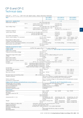
CP-S and CP-C
Technical data

Data at Ta = 25 °C, Uin = 230 V AC and rated values, unless otherwise indicated

Type                                                                            CP-C 24/5.0                 CP-C 24/10.0           CP-C 24/20.0
                                                                                                            CP-S 24/10.0           CP-S 24/20.0
                                                                                CP-S 24/5.0

Input circuit - supply circuit                                                                                   L, N

Rated input voltage Uin                                               CP-C 110-240 V AC
                                                   switch position 115 110-240 V AC
                                             CP-S                                                     110-120 V AC

                                                   switch position 230                                220-240 V AC

Input voltage range                                             CP-C 85-264 V AC / 100-350 V DC 1)

                                             CP-S  switch position 115 85-264 V AC / 100-             85-132 V AC
                                                   switch position 230 350 V DC 1)                    184-264 V AC / 220-350 V DC 1)
                                                                                                                                                                 3
Frequency range AC                                                      47-63 Hz

Typical input current                        CP-S and CP-C at 110-240 V AC 2.2-1.2 A                  2.6-1.2 A                    5.5-2.5 A
Typ. power consumption                                      CP-S at 110-120 V AC -                    4.2-4.0 A                    9.0-8.0 A
                                                           CP-S at 220-240 V AC -                     2.4-2.2 A                    4.5-4.0 A
                                                                                             135 W    269 W                        538 W

Inrush current limiting / I2t ( cold start)                     CP-C < 23 A / approx.                 < 33 A / approx. 0.2 A2s < 40 A / approx. 1.9 A2s
                                                                CP-S 0.9 A2s                          < 40 A / approx. 1.8 A2s < 70 A / approx. 8 A2s

Power failure buffering time                                            min. 100 ms                   min. 40 ms                   min. 40 ms

Transient overvoltage protection                                        varistors

Internal input fuse (apparatus protection, not accessible)              4 A (slow-acting)             6.3 A (slow-acting)          12 A (fast-acting)

Power factor correction (PFC)                                   CP-C yes, active

                                                                CP-S no

Indication of operational states                   OUTPUT OK: green LED V: output voltage OK
Output voltage

Output circuit                                                                     L+, L+, L-, L- : short-circuit, no-load and overload proof
Rated output voltage                                                    24 V DC

Tolerance of the output voltage                                 CP-C ±1 %

                                                                CP-S -1...+5 %

Adjustment range of the output                                  CP-C 22-28 V DC, default setting 24 V ±0.5 %
voltage                                                         CP-S fixed

Rated output power                                                      120 W                         240 W                        480 W

Rated output current                                            Ta ͨ 60 °C 5 A                        10 A                         20 A
Peak output current (power reserve)                                                                                                typ. ͨ 22.5 A
Derating                                                        Ta ͨ 40 °C typ. ͨ 7.25 A              typ. ͨ 12.25 A
Deviation with
                                                   60 °C < Ta ͨ 70 °C 2.5 % per Kelvin temperature increase
Control time
                                             CP-C  load change statical 10-90 % typ. < ±0.05 %

                                             CP-S load change statical 10-90 % typ. < ±0.1 %

                                                   load change dynamical 10-90 % typ. < ±3 %

                                             change of the input voltage of ±10 % typ. < ±0.05 %

                                                                        typ. < 1 ms

Starting time after applying                                    CP-C < 200 ms                         < 200 ms                     typ. < 200 ms
supply voltage                                                  CP-S                                  < 250 ms                     typ. < 300 ms

Rise time 10-90 %                                               CP-C typ. < 30 ms                     typ. < 4 ms                  typ. < 12 ms

                                                                CP-S                                  typ. < 5 ms                  typ. < 15 ms

Residual ripple and switching peaks                         BW = 20 MHz typ. < 50 mVPP
Parallel connection                                                              yes, up to 5 devices, to enable redundancy and to increase
                                                                                 power, current not symmetrical (CP-S only redundancy)

Series connection                                                       yes, to increase voltage, for decoupling refer to the application manual
Resistance to reverse feed                                              approx. 35 V DC

Output circuit - No-load, overload and short-circuit behaviour                                      see also U/I- and I/T-characteristic curves

Characteristic curve of output                                          U/I characteristic curve with power reserve
Current limiting at short circuit
Short-circuit protection                                                approx. 11 A                  approx. 19 A                 approx. 25 A
Overload protection
Starting of capacitive loads                                            continuous short-circuit stability

                                                                        thermal protection

                                                                        unlimited

General data

Power dissipation                                                       typ. < 15 W                   typ. < 29 W                  typ. < 58 W

Efficiency                                                              typ. 89 %
Discharge current for PE                                                < 3.5 mA

MTBF                                                            CP-C 500.000 h

Dimensions (W x H x D)                                          CP-S 350.000 h                        90 (93.5 2)) x 130 x 135.5   200 (203.5 2)) x 130 x 135.5
                                                                                                      mm (3.54 (3.68 2)) x 5.12 x  mm (7.87 (8.01 2)) x 5.12 x
                                                                         56.5 (60 2)) x 130 x 135.5   5.35 in)                     5.35 in)
                                                                         mm (2.22 (2.36 2)) x 5.12 x
                                                                         5.35 in)

Weight                                                          CP-C approx. 0.96 kg (2.12 lb) approx. 1.34 kg (2.95 lb) approx. 3.15 kg (6.94 lb)

                                                                CP-S                                  approx. 1.07 kg (2.36 lb) approx. 2.83 kg (6.23 lb)

Minimum distance to other units                    horizontal / vertical 10 mm / 80 mm (0.39 in / 3.15 in)

Degree of protection                                 housing / terminals IP20 / IP20
Material of housing                                housing shell / cover aluminium / zinc-coated sheet steel
Protection class (EN 61140)
                                                                                  I

Mounting                                                                DIN rail (IEC/EN 60715), snap-on mounting
Mounting position                                                       horizontal

                                                                2CDC 110 004 C0210 | Catalog Electronic Products and Relays 2015 | ABB 3/46