
Page 33 - EPR Catalog 2015
P. 33
CT-E range
Function diagrams
Remarks Terminal designations on the device and in the diagrams 1
The c/o contact is always designated 15-16/18.
Legend The n/o contacts are designated with 15-16 and 15-18.
G Control supply voltage not applied / Output contact open Control supply voltage is always applied to terminals
B Control supply voltage applied / Output contact closed A1-A2/B1.
A1-Y1/B1: Control input with voltage-related triggering
Function of the red LED
The red LED R glows as soon as the output relay energizes
and turns off when the output relay de-energizes.
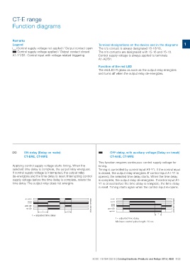
A ON-delay (Delay on make) B OFF-delay, with auxiliary voltage (Delay on break)
CT-ERE, CT-MFE CT-AHE, CT-MFE
Applying control supply voltage starts timing. When the This function requires continuous control supply voltage for
selected time delay is complete, the output relay energizes. timing.
If control supply voltage is interrupted, the output relay Timing is controlled by control input A1-Y1. If the control input
de-energizes and the time delay is reset. Interrupting control is closed, the output relay energizes. If control input A1-Y1 is
supply voltage before the time delay is complete, resets the opened, the selected time delay starts. When the time delay
time delay. The output relay does not energize. is complete, the output relay de-energizes. If control input A1-
Y1 is closed before the time delay is complete, the time delay
is reset. Timing starts again when the control input re-opens.
A1-A2/B1 2CDC 252 130 F0205
15-18 2CDC 252 132 F0205
15-16 A1-A2
A1-Y1
green LED 15-18
red LED 15-16
green LED
t <t red LED
t = adjusted time delay t = adjusted time delay t
Minimum control pulse length: 20 ms
2CDC 110 004 C0210 | Catalog Electronic Products and Relays 2015 | ABB 1/22