
Page 36 - EPR Catalog 2015
P. 36
CT-E range
Function diagrams
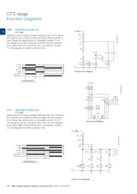
FA Star-delta change-over L1 F3
CT-YDE
1 95
Applying control supply voltage energizes the star contactor F2 96 2CDC 253 002 F0013
S1 21
(K1) and the line contactor (K2) and begins the set starting
time. When the starting time is complete, contact 15-16 0 22
de-energizes the star contactor (K1) Now, the fix transition S2 13
time starts. When the transition time is complete, contact I
14
15-16 energizes the delta contactor (K3). 21
K2
22
21 43 13 13
K3 22 K1 K2 K1
44 14 14
16
21 15
K1 K1T
22
A1-A2/B1 2CDC 252 133 F0206 A1 A1 A1 A1
15-18
15-16 K1 K1T K3 K2
green LED A2 A2 A2 A2
red LED
N N
Star contactor
Delta contactor Yͬ
Control circuit diagram
t1 t2
t1 = adjustable starting time L1 L2 L3
t2 = fixed transition time of 50 ms
135
2CDC 253 009 F0012
-F1
246
135 135 135
-K3 2 4 6 -K1 2 4 6
-K2 2 4 6
FC Star-delta change-over 154 97 95
98 96
CT-SDE -F2
Applying control supply voltage energizes the star contactor
(K1) and the line contactor (K2) and begins the set starting 326
time. When the starting time is complete, contact 15-16
de-energizes the star contactor (K1). Now, the fix transition -M1 W2
time starts. When the transition time is complete, contact V2
15-18 energizes the delta contactor (K3). W1 U2
V1 M
U1 3 ~
Power circuit diagram
L1 F3
F2 95 2CDC 253 001 F0013
S1
96
0 21
22
A1-A2/B1 2CDC 252 134 F0206 S2 13 53
15-18 I
15-16 K2
14
green LED 54
red LED
15 15 13 53
Star contactor 18
Delta contactor K1T K1T K2 K1
16 14 54
t1 t2 22 22
t1 = adjustable starting time K3 21 K1 21
t2 = fixed transition time of 30 ms
B1 A1 A1 A1 A1
K1T K1 K3 K2
A2 A2 A2 A2
N
Y ͬN
Control circuit diagram
1/25 ABB | Catalog Electronic Products and Relays 2015 | 2CDC 110 004 C0210