Page 35 - EPR Catalog 2015
P. 35

CT-E range
Function diagrams

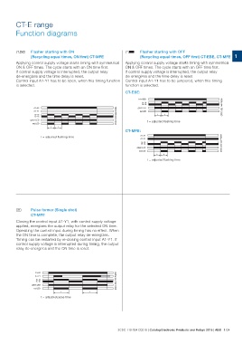
DA Flasher starting with ON                                      DB Flasher starting with OFF                                                    1

            (Recycling equal times, ON first) CT-MFE                         (Recycling equal times, OFF first) CT-EBE, CT-MFE

Applying control supply voltage starts timing with symmetrical   Applying control supply voltage starts timing with symmetrical
ON & OFF times. The cycle starts with an ON time first.          ON & OFF times. The cycle starts with an OFF time first.
If control supply voltage is interrupted, the output relay       If control supply voltage is interrupted, the output relay
de-energizes and the time delay is reset.                        de-energizes and the time delay is reset.
Control input A1-Y1 has to be open, when this timing function    Control input A1-Y1 has to be jumpered, when this timing
is selected.                                                     function is selected.

                                                                 CT-EBE:

     A1-A2                                  2CDC 252 026 F0209   A1-A2/B1                                                    2CDC 252 140 F0205
     A1-Y1                                                             15-18
      15-18                                                            15-16
      15-16
green LED                                                        green LED
   red LED                                                          red LED

                                                                                                 tt

                                                                                                 t = adjusted flashing time

             tt

             t = adjusted flashing time                          CT-MFE:                                                     2CDC 252 023 F0209

                                                                                         A1-A2
                                                                                         A1-Y1
                                                                                          15-18
                                                                                          15-16
                                                                                   green LED
                                                                                       red LED

                                                                                                 tt

                                                                                                 t = adjusted flashing time

H Pulse former (Single shot)
            CT-MFE

Closing the control input A1-Y1, with control supply voltage
applied, energizes the output relay for the selected ON time.
Operating the control input during timing has no effect. When
the ON time is complete, the output relay de-energizes.
Timing can be restarted by re-closing control input A1-Y1. If
control supply voltage is interrupted during timing, the output
relay de-energizes and the ON time is reset.

     A1-A2                                  2CDC 252 136 F0205
     A1-Y1
      15-18
      15-16
green LED
   red LED

                 t                       t

             t = adjusted pulse time

                                                                2CDC 110 004 C0210 | Catalog Electronic Products and Relays 2015 | ABB 1/24
   30   31   32   33   34   35   36   37   38   39   40