
Page 37 - EPR Catalog 2015
P. 37
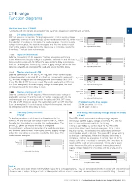
CT-E range
Function diagrams

Multifunction timer CT-MKE                                                                                                                                                1
Functions and time ranges are programmed by simply plugging in external wire jumpers.

A ON-delay (Delay on Make)

Without external connection. Timing begins when control supply voltage               A1-A2                                        2CDC 252 146 F0205

is applied to terminal A1 and the load connected in series with A2. When Thyristor A1-A2

the selected time delay is complete, the load energizes. If control supply           red LED
voltage is interrupted, the load de-energizes and the time delay is reset.
                                                                                               t                           <t

Interrupting supply voltage before the time delay is complete, resets the                      t = adjusted time delay

time delay. The load does not energize.

CA Impulse-ON (Interval)

External connection X1-X4 required. The load energizes and timing                    A1-A2                                        2CDC 252 147 F0205

starts when control supply voltage is applied to terminal A1 and the load Thyristor A1-A2

connected in series with A2. When the selected time delay is complete,               red LED
the load de-energizes. Interrupting control supply voltage before the time
                                                                                                  t                        <t

delay is complete, de-energizes the load and resets the time delay.                            t = adjusted pulse time

DA Flasher, starting with ON                                                            A1-A2                                     2CDC 252 148 F0205
External connection X1-X4 and X2-X4 required. When control supply           Thyristor A1-A2
voltage is applied to terminal A1 and the load connected in series with
A2, the load energizes and de-energizes with the selected ON & OFF                    red LED
times. The ON & OFF times are equal. The cycle starts with an ON time
first (load energized). If control supply voltage is interrupted, the load                     tt
de-energizes and the time delay is reset.
                                                                                               t = adjusted flashing time
DB Flasher, starting with OFF
External connection X2-X4 required. When control supply voltage is                      A1-A2                                     2CDC 252 149 F0205
applied to terminal A1 and the load connected in series with A2, the        Thyristor A1-A2
load energizes and de-energizes with the selected ON & OFF times.
The ON & OFF times are equal. The cycle starts with an OFF time first                 red LED
(load de-energized). If control supply voltage is interrupted, the load
de-energizes and the time delay is reset.                                                      tt

                                                                                               t = adjusted flashing time

                                                                                     Programming the time ranges
                                                                                     X3-X4 jumpered: 0.1-10 s
                                                                                     X3-X4 open: 3-300 s

A ON-delay (Delay on make)                                          B OFF-delay, with auxiliary voltage (Delay on break)

            CT-EKE                                                          CT-AKE

Timing begins when control supply voltage is applied to             The OFF-delay function with auxiliary voltage requires
terminal A1 and the load connected in series with AL. When          continuous control supply voltage at terminal A1, and the
the selected time delay is complete, the load energizes. The        load connected in series with AL, for timing.
green LED glows as long as the load is energized.                   Timing is controlled by control input Y2-A2. When the
If control supply voltage is interrupted, the load de-energizes     control input is closed, the load energizes. If the control
and the time delay is reset. Interrupting control supply voltage    input is opened, the selected time delay starts (minimum
before the time delay is complete, resets the time delay. The       control pulse length is 20 ms). The green LED glows as long
load does not energize.                                             as the load is energized. When the selected time delay is
                                                                    complete, the load de-energizes. If control input Y2-A2 is
            A1-AL                               2CDC 252 150 F0205  closed before the time delay is complete, the time delay is
Thyristor A1-AL                                                     reset and the load remains energized. Timing starts again
                                                                    when the control input is re-opened. Interrupting control
      green LED                                                     supply voltage resets the time delay and de-energizes the
                                                                    load.
                   t                        <t

                   t = adjusted time delay                                  A1-AL                                                                     2CDC 252 001 F0213

                                                                            Y2-A2

                                                                    Thyristor A1-AL

                                                                     green LED

                                                                                     t = adjusted time delay                   t

Notice:
CT-...KE are solid-state timers with thyristor output for 2-wire applications. They are connected directly in series with the control coil
of contactors or relays. Voltage should not be applied without a load connected, because there is no current limiting in the unit.

                                                                    2CDC 110 004 C0210 | Catalog Electronic Products and Relays 2015 | ABB 1/26