
Page 678 - Motor_protection_and_control_Manual_motor_starters_ contactors
P. 678
AF09..S ... AF26..S 3-pole contactors - with spring terminals
Technical data
Magnet system characteristics
Contactor types AC / DC operated AF09..S AF12..S AF16..S AF26..S
Coil operating limits AC supply At θ ≤ 60 °C 0.85 x Uc min...1.1 x Uc max.
acc. to IEC 60947-4-1 At θ ≤ 70 °C 0.85 x Uc min...Uc max.
DC supply At θ ≤ 60 °C 0.85 x Uc min...1.1 x Uc max.
At θ ≤ 70 °C (AF) 0.85 x Uc min...Uc max. - (AF..Z) 0.85 x Uc min...1.1 x Uc max.
AC control voltage Rated control circuit voltage Uc 24...500 V AC
50/60 Hz Coil consumption Average pull-in value (AF) 50 VA - (AF..Z) 16 VA
Average holding value (AF) 2.2 VA / 2 W - (AF..Z) 1.7 VA / 1.5 W
DC control voltage Rated control circuit voltage Uc 12...500 V DC
Coil consumption Average pull-in value (AF) 50 W - (AF..Z) 12...16 W
Average holding value (AF) 2 W - (AF..Z) 1.7 W
PLC-output control (AF..Z) ≥ 500 mA 24 V DC
Drop-out voltage ≤ 60 % of Uc min.
Voltage sag immunity (AF..Z) conditions of use on request
acc. to SEMI F47-0706
Dips withstand (AF..Z) 22 ms average for Uc ≥ 24 V 50/60 Hz or Uc ≥ 20 V DC
-20 °C ≤ θ ≤ +60°C
6 Operating time
Between coil energization and: N.O. contact closing 40...95 ms
N.C. contact opening 38...90 ms
Between coil de-energization and: N.O. contact opening 11...95 ms
N.C. contact closing 13...98 ms
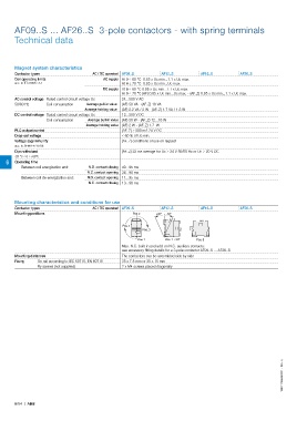
Mounting characteristics and conditions for use
Contactor types AC / DC operated AF09..S AF12..S AF16..S AF26..S
Mounting positions Pos. 2 +30° -30°
Pos. 4
Pos. 3
Pos. 1 Pos. 1 ± 30° Pos. 5
Max. N.C. built-in and add-on N.C. auxiliary contacts:
see accessory fitting details for a 3-pole contactor AF09..S ... AF26..S
Mounting distances The contactors can be assembled side by side
Fixing On rail according to IEC 60715, EN 60715 35 x 7.5 mm or 35 x 15 mm
By screws (not supplied) 2 x M4 screws placed diagonally
1SBC101689S0201 - Rev. A
6/54 | ABB