
Page 22 - Current & voltage sensors catalog
P. 22
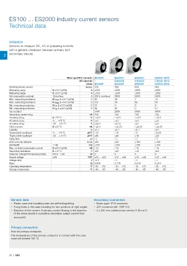
ES100 ... ES2000 industry current sensors
       Technical data


       Utilisation
       Sensors to measure DC, AC or pulsating currents
       with a galvanic insulation between primary and
    2  secondary circuits.


                                            Molex type HE14 connector ES100C  ES300C   ES500C       ES500-9672
                                                   JST connector –        ES300S       ES500S       ES500-9673
                                                        Cables ES100F     ES300F       ES500F       ES500-9674
       Nominal primary current                          A r.m.s. 100      300          500          500
       Measuring range            @ ±15 V (±5%)            A  ±150        ±500         ±800         ±800
       Measuring range            @ ±24 V (±5%)            A  ±150        ±500         ±800         ±800
       Not measurable overload    10 ms/hour               A  300 (1 ms/hour)  3000    5000         5000
       Max. measuring resistance  @ I PMAX & ±15 V (±5%)   Ω 50           20           7            13
       Max. measuring resistance  @ I PMAX & ±24 V (±5%)   Ω 107          54           60           56
       Min. measuring resistance  @ I PN & ±15 V (±5%)     Ω 12           0            0            0
       Min. measuring resistance  @ I PN & ±24 V (±5%)     Ω 89           45           0            31
       Turn number                                           1000         2000         5000         4000
                                                          mA 100          150          100          125
       Secondary current at I PN
                                  @ +25 °C                 % ≤±0.5        ≤±0.5        ≤±0.5        ≤±0.5
       Accuracy at I PN
       Accuracy at I PN           -5 … +70 °C              % ≤±1          ≤±1          ≤±1          ≤±1
       Accuracy at I PN           -20 … +70 °C             % ≤±2.5        ≤±1.5        ≤±1          ≤±1
       Offset current             @ +25 °C                mA ≤±0.4        ≤±0.25       ≤±0.25       ≤±0.25
       Linearity                                           % ≤0.1         ≤0.1         ≤0.1         ≤0.1
       Thermal drift coefficient  -5 … +70 °C           μA/°C ≤10         ≤15          ≤5           ≤6.25
       Thermal drift coefficient  -20 … +70 °C          μA/°C ≤80         ≤40          ≤16          ≤20
       Delay time                                          μs ≤1          ≤1           ≤1           ≤1
       di/dt correctly followed                          A / μs ≤50       ≤50          ≤100         ≤100
       Bandwidth                  -1 dB                   kHz ≤100        ≤100         ≤100         ≤100
       Max. no-load consumption current  @ ±24 V (±5%)    mA ≤12          ≤12          ≤12          ≤12
       Secondary resistance       @ +70 °C                 Ω ≤30          ≤33          ≤76          ≤53
       Dielectric strength Primary/Secondary  50 Hz, 1 min  kV 3          3            3            3
       Supply voltage             ±5%                    V DC ±12 … ±24   ±12 … ±24    ±12 … ±24    ±12 … ±24
       Voltage drop                                        V ≤2.5         ≤1           ≤1           ≤1
       Mass                                               kg 0.050        0.115        0.210        0.210
       Operating temperature                              °C -20 … +70    -20 … +70    -20 … +70    -20 … +70
       Storage temperature                                °C -40 … +85    -40 … +85    -40 … +85    -40 … +85


        General data                                         Secondary connection
           – Plastic case and insulating resin are self-extinguishing    – Molex type HE14 connector
           – Fixing holes in the case moulding for two positions at right angles    – JST connector (ref.: B3P-VH)
           – Direction of the current: A primary current flowing in the direction     – 3 x 200 mm cables (cross section 0.38 mm²).
          of the arrow results in a positive secondary output current from
          terminal M.


        Primary connection
        Hole for primary conductor.
        The temperature of the primary conductor in contact with the case
        must not exceed 100 °C.


       20  |  ABB