Page 31 - 1SNC160019C0203_SNA series - Terminal blocks
P. 31
D240/36.D10 screw clamp terminal blocks
Feed-through - 36 mm 1.417 in spacing
Description
240 mm²
– Closed terminal block: no end section needed, optimized rigidity,
– Ease your voltage monitoring or distribution with the 2 built-in derivations,
– Use of jumper bars requires the user to cut out the partition.
Ordering details 2
Description Color Type Order code Pkg Weight
qty (1 pce) g
Feed-through Closed block with Grey D240/36.D10 1SNA399704R1200 5 542.00
2 x 10 mm² derivations. Yellow D240/36.D10.N 1SNA399706R1400 5 5 542.00
Blue
D240/36.D10.YL
1SNA400779R0000
542.00
1SNC161003F0014 Main technical data Mounting instructions
CSA
IEC
Rail
TH 35-7.5,
UL
Connecting capacity
TH 35-15
Main circuit with Rigid - Solid / Stranded 50-300 mm² Main circuit
1 conductor per Flexible 35-240 mm² Wire stripping 35 mm
clamp with insulated ferrule length 1.37 in
Gauge B14 Allen key
Derivation with Rigid - Solid / Stranded 0.5-16 mm² Tool Ø 8 mm
1 conductor per Flexible 0.5-10 mm² Ø 0.39 in
D240/36.D10 clamp with insulated ferrule Torque 10 - 15 N.m
Gauge B6 89 - 132 lb.in
Rated current / Rated cross section Derivation
Main circuit 415 A / 240 mm² Wire stripping 12 mm
119.4 4.70" Derivation 57 A / 10 mm² length 0.47 in
110 4.33" Rated short-time withstand current (1s) 28800 A Flat screwdriver
Rated voltage 1000 V Tool Ø 4 mm
Impulse withstand voltage 8000 V Ø 0.157 in
Protection IP10 NEMA Torque 1.2 - 1.4 N.m
124.5 4.90" The connecting capacity data for one Rigid - Solid / Stranded - Flexible conductor (when applicable) is a mandatory information required by IEC, UL and CSA standards.
10.6 - 12.3 lb.in
All other data are provided as supplementary information only. For more details, please consult our CB, UL or CSA certificates and technical datasheet available on http://www.abb.com
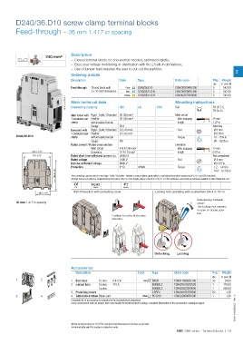
CE RoHS Gost R
IP20 Protection with protecting cover Locking foot operating with screwdriver DIA 4 0.157 in
36.5 1.43"
Sideopening "bistable
36 mm 1.417 in spacing action".
The locking foot remains
in open or closed posi-
tion.
Partition to cut to fit the wire
diameter.
Unlocking Locking
Accessories
Description Color Type Order code Pkg Weight
qty (1 pce) g
1 2 1 End stops 12 mm 0.472 in Grey BADH 1SNA116900R2700 50 24.00
2 Jumper bars 2 poles 415 A BJMI36.2 1SNA206126R2500 1 170.00
3 poles BJMI36.3 1SNA206223R0600 1 260.00
3 Protecting covers CPBP2 1SNA399787R0500 20 1.30
1SNC161032S0201 - Rev. A
3 4 4 Terminal block markersBlank card White RC1010 1SNA238000R1600 1 1.30
Complete list of accessories is indicated in the terminal block datasheet.
Some accessories such as jumper bars may modify the terminal block’s ratings: complete information in the accessories catalogue pages.
All the technical data for UL/CSA standard and dimensions in inches are in italic.
Technical data valid for copper conductors only.
ABB SNA series - Terminal blocks | 29
Feed-through - 36 mm 1.417 in spacing
Description
240 mm²
– Closed terminal block: no end section needed, optimized rigidity,
– Ease your voltage monitoring or distribution with the 2 built-in derivations,
– Use of jumper bars requires the user to cut out the partition.
Ordering details 2
Description Color Type Order code Pkg Weight
qty (1 pce) g
Feed-through Closed block with Grey D240/36.D10 1SNA399704R1200 5 542.00
2 x 10 mm² derivations. Yellow D240/36.D10.N 1SNA399706R1400 5 5 542.00
Blue
D240/36.D10.YL
1SNA400779R0000
542.00
1SNC161003F0014 Main technical data Mounting instructions
CSA
IEC
Rail
TH 35-7.5,
UL
Connecting capacity
TH 35-15
Main circuit with Rigid - Solid / Stranded 50-300 mm² Main circuit
1 conductor per Flexible 35-240 mm² Wire stripping 35 mm
clamp with insulated ferrule length 1.37 in
Gauge B14 Allen key
Derivation with Rigid - Solid / Stranded 0.5-16 mm² Tool Ø 8 mm
1 conductor per Flexible 0.5-10 mm² Ø 0.39 in
D240/36.D10 clamp with insulated ferrule Torque 10 - 15 N.m
Gauge B6 89 - 132 lb.in
Rated current / Rated cross section Derivation
Main circuit 415 A / 240 mm² Wire stripping 12 mm
119.4 4.70" Derivation 57 A / 10 mm² length 0.47 in
110 4.33" Rated short-time withstand current (1s) 28800 A Flat screwdriver
Rated voltage 1000 V Tool Ø 4 mm
Impulse withstand voltage 8000 V Ø 0.157 in
Protection IP10 NEMA Torque 1.2 - 1.4 N.m
124.5 4.90" The connecting capacity data for one Rigid - Solid / Stranded - Flexible conductor (when applicable) is a mandatory information required by IEC, UL and CSA standards.
10.6 - 12.3 lb.in
All other data are provided as supplementary information only. For more details, please consult our CB, UL or CSA certificates and technical datasheet available on http://www.abb.com
CE RoHS Gost R
IP20 Protection with protecting cover Locking foot operating with screwdriver DIA 4 0.157 in
36.5 1.43"
Sideopening "bistable
36 mm 1.417 in spacing action".
The locking foot remains
in open or closed posi-
tion.
Partition to cut to fit the wire
diameter.
Unlocking Locking
Accessories
Description Color Type Order code Pkg Weight
qty (1 pce) g
1 2 1 End stops 12 mm 0.472 in Grey BADH 1SNA116900R2700 50 24.00
2 Jumper bars 2 poles 415 A BJMI36.2 1SNA206126R2500 1 170.00
3 poles BJMI36.3 1SNA206223R0600 1 260.00
3 Protecting covers CPBP2 1SNA399787R0500 20 1.30
1SNC161032S0201 - Rev. A
3 4 4 Terminal block markersBlank card White RC1010 1SNA238000R1600 1 1.30
Complete list of accessories is indicated in the terminal block datasheet.
Some accessories such as jumper bars may modify the terminal block’s ratings: complete information in the accessories catalogue pages.
All the technical data for UL/CSA standard and dimensions in inches are in italic.
Technical data valid for copper conductors only.
ABB SNA series - Terminal blocks | 29