
Page 374 - EPR Catalog 2015
P. 374
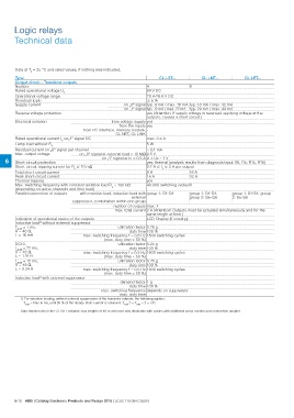
Logic relays
Technical data

Data at Ta = 25 °C and rated values, if nothing else indicated.

Type                                                                                                       CL-LST...        CL-LMT...                     CL-LET...

Output circuit - Transistor outputs

Number                                                                       48

Rated operational voltage Ue                                                 24 V DC

Operational voltage range                                                    20.4-28.8 V DC

Residual ripple                                                              ͨ5%

Supply current                                                   on „0“ signal typ. 9 mA / max. 16 mA typ. 18 mA / max. 32 mA

                                                                 on „1“ signal typ. 12 mA / max. 22 mA typ. 24 mA / max. 44 mA

Reverse voltage protection                                                   yes (Attention: If supply voltage is reversed, applying voltage at the
                                                                             outputs, causes a short circuit.)

Electrical isolation                             from voltage supply yes

                                                 from the inputs yes

                                     from PC interface, memory module, -
                                                               CL-NET, CL-LINK

Rated operational current Ie on„1“ signal DC                                 max. 0.5 A

Lamp load without Rv                                                         5W

Residual current on „0“ signal per channel                                   < 0.1 mA

Max. output voltage                  on „0“ signal at external load < 10 M⏲ 2.5 V

6 Short-circuit protection                       on „1“ signal at Ie = 0.5 A U = Ue - 1 V
                                                                                     yes, thermal (analysis results from diagnosis input I16, I15; R15, R16)

Short-circuit tripping current for Ra ͨ 10 m⏲                                0.7 A ͨ Ie ͨ 2 A per output

Total short-circuit current                                                  8 A 16 A

Peak short-circuit current                                                   16 A                                     32 A

Thermal tripping                                                             yes

Max. switching frequency with constant resistive load RL < 100 k⏲            40.000 switching cycles/h
(depending on active channels and their load)

Parallel connection of outputs       with resistive load, inductive load with group 1: Q1-Q4                          group 1: Q1-Q4,  group 1: S1-S4, group
                                                                                                                      group 2: Q5-Q8   2: S5-S8
                                                                   external

                                suppressor, combination within one group

                                                 number of outputs max. 4

                                                 max. total current 2 A (Attention! Outputs must be actuated simultaneously and for the
                                                                           same length of time.)

Indication of operational states of the outputs                              LCD-Display (if existing)

Inductive load1) without external suppressor

T0.95 = 1 ms,                                                    utilization factor 0.25 g
R = 48 ⏲,                                                                 duty time 100 %
L = 16 mH
                                     max. switching frequency f = 0,5 Hz 1500 switching cycles
                                                      (max. duty time = 50 %)

DC13,                                                            utilization factor 0.25 g
                                                                          duty time 100 %
T0.95  = 72 ms,
R=     48 ⏲,                         max. switching frequency f = 0,5 Hz 1500 switching cycles
                                                      (max. duty time = 50 %)
L = 1.15 H

T0.95  = 15 ms,                                                  utilization factor 0.25 g
R=     48 ⏲,                                                              duty time 100 %

L = 0.24 H                           max. switching frequency f = 0,5 Hz 1500 switching cycles
                                                      (max. duty time = 50 %)

Inductive load1) with external suppressor

                                                 demand factor 1 g

                                                                 duty time 100 %

                                                 max. switching frequency depends on suppressor
                                                                max. duty time

1) For inductive loading, without external suppression of the transistor outputs, the following applies:

       T0.95 = time in ms, until 95 % of the steady-state current is achieved. T0.95 3 × T0.65 = 3 × L/R.

Data transfer rate in the CL-NET network: bus lengths of 40 m and over only attainable with cables with additional cross-section and connection adapter.

6/15 ABB | Catalog Electronic Products and Relays 2015 | 2CDC 110 004 C02010