
Page 172 - PLC Automation
P. 172
170 MAIN CATALOG PLC AUTOMATION
—
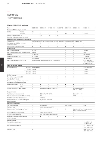
AC500-XC
Technical data
Digital S500-XC I/O modules
Type DI524-XC DC522-XC DC523-XC DC532-XC DO524-XC DO526-XC DX522-XC
Number of channels per module
Digital inputs 32 – – 16 – – 8
outputs – – – – 32 8 8 relays
Configurable channels DC – 16 24 16 – – –
(configurable as inputs or outputs)
Additional configuration of channels as
Fast counter configuration of max. 2 channels per module, operating modes see table on page 192
Occupies max. 1 DO or DC when – – – –
used as counter
Connection via terminal unit
Digital inputs
Input signal voltage 24 V DC – – 24 V DC
Input characteristic acc. to EN 61132-2 Type 1 – – Type 1
0 signal -3...+5 V DC – – -3...+5 V DC
Undefined signal state 5...15 V DC – – 5...15 V DC
1 signal 15...30 V DC – – 15...30 V DC
Input time delay (0 -> 1 or 1 -> 0) 8 ms typically, configurable from 0.1 up to 32 ms – – 8 ms typically,
configurable from
0.1 up to 32 ms
Input current per channel
05
At input voltage 24 V DC 5 mA typically – – 5 mA typically
5 V DC > 1 mA – – > 1 mA
15 V DC > 5 mA – – > 5 mA
30 V DC < 8 mA – – < 8 mA
Digital outputs
Transistor outputs 24 V DC – –
Readback of output – – – –
Relay outputs, supplied via process – – – – – –
voltage UP, changeover contacts
Switching of load 24 V –
230 V – – – – – –
Output voltage at signal state 1 – process voltage UP minus 0.8 V process voltage –
UP minus 0.4 V
Output current
Nominal current per channel – 500 mA at UP = 24 V 2 A at UP = 24 V –
Maximum (total current of all channels) – 8 A 16 A –
Residual current at signal state 0 – < 0.5 mA –
Demagnetization when switching off – by internal varistors –
inductive loads
Switching frequency
For inductive load – 0.5 Hz max. 0.5 Hz max. 2 Hz
For lamp load – 11 Hz max. at max. 5 W
Short-circuit / overload proofness – by external fuse / circuit breaker
6 A gL/gG per channel
Overload indication (I > 0.7 A) – after approx. 100 ms –
Output current limiting – yes, with automatic reclosure –
Proofness against reverse feeding – –
of 24 V signals
Contact rating
For resistive load, max. – 3 A at 230 V AC
2 A at 24 V DC
For inductive load, max. – 1.5 A at 230 V AC
1.5 A at 24 V DC
For lamp load – 60 W at 230 V AC
10 W at 24 V DC