
Page 175 - PLC Automation
P. 175
AC500 -XC – PLC OPER ATING IN EXTREME CONDITIONS 173
—
AC500-XC
Technical data
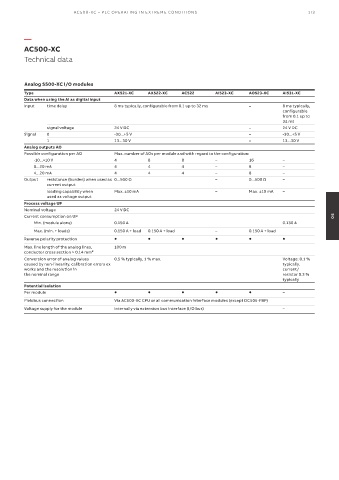
Analog S500-XC I/O modules
Type AX521-XC AX522-XC AC522 AI523-XC AO523-XC AI531-XC
Data when using the AI as digital input
Input time delay 8 ms typically, configurable from 0.1 up to 32 ms – 8 ms typically,
configurable
from 0.1 up to
32 ms
signal voltage 24 V DC – 24 V DC
Signal 0 -30...+5 V – -30...+5 V
1 13...30 V – 13...30 V
Analog outputs AO
Possible configuration per AO Max. number of AOs per module and with regard to the configuration:
-10...+10 V 4 8 8 – 16 –
0...20 mA 4 4 4 – 8 –
4...20 mA 4 4 4 – 8 –
Output resistance (burden) when used as 0...500 Ω – 0...500 Ω –
current output
loading capability when Max. ±10 mA – Max. ±10 mA –
used as voltage output
Process voltage UP
Nominal voltage 24 V DC
Current consumption on UP 05
Min. (module alone) 0.150 A 0.130 A
Max. (min. + loads) 0.150 A + load 0.150 A + load – 0.150 A + load
Reverse polarity protection
Max. line length of the analog lines, 100 m
conductor cross section > 0.14 mm²
Conversion error of analog values 0.5 % typically, 1 % max. Voltage: 0.1 %
caused by non-linearity, calibration errors ex typically,
works and the resolution in current/
the nominal range resistor 0.3 %
typically
Potential isolation
Per module –
Fieldbus connection Via AC500-XC CPU or all communication interface modules (except DC505-FBP)
Voltage supply for the module Internally via extension bus interface (I/O bus) –