
Page 177 - PLC Automation
P. 177
AC500 -XC – PLC OPER ATING IN EXTREME CONDITIONS 175
—
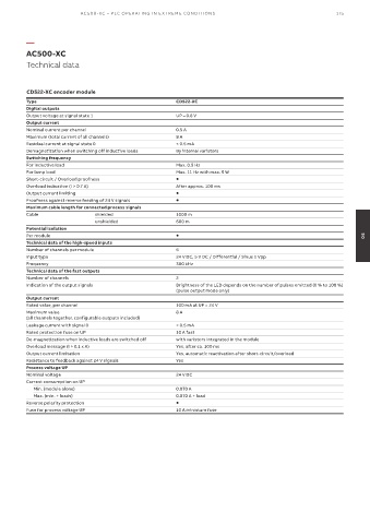
AC500-XC
Technical data
CD522-XC encoder module
Type CD522-XC
Digital outputs
Output voltage at signal state 1 UP – 0.8 V
Output current
Nominal current per channel 0.5 A
Maximum (total current of all channels) 8 A
Residual current at signal state 0 < 0.5 mA
Demagnetization when switching off inductive loads By internal varistors
Switching frequency
For inductive load Max. 0.5 Hz
For lamp load Max. 11 Hz with max. 5 W
Short-circuit / Overload proofness
Overload indication (I > 0.7 A) After approx. 100 ms
Output current limiting
Proofness against reverse feeding of 24 V signals
Maximum cable length for connected process signals
Cable shielded 1000 m
unshielded 600 m
Potential isolation
Per module 05
Technical data of the high-speed inputs
Number of channels per module 6
Input type 24 V DC, 5 V DC / Differential / Sinus 1 Vpp
Frequency 300 kHz
Technical data of the fast outputs
Number of channels 2
Indication of the output signals Brightness of the LED depends on the number of pulses emitted (0 % to 100 %)
(pulse output mode only)
Output current
Rated value, per channel 100 mA at UP = 24 V
Maximum value 8 A
(all channels together, configurable outputs included)
Leakage current with signal 0 < 0.5 mA
Rated protection fuse on UP 10 A fast
De-magnetization when inductive loads are switched off with varistors integrated in the module
Overload message (I > 0.1 x A) Yes, after ca. 100 ms
Output current limitation Yes, automatic reactivation after short-circuit/overload
Resistance to feedback against 24 V signals Yes
Process voltage UP
Nominal voltage 24 V DC
Current consumption on UP
Min. (module alone) 0.070 A
Max. (min. + loads) 0.070 A + load
Reverse polarity protection
Fuse for process voltage UP 10 A miniature fuse