
Page 180 - PLC Automation
P. 180
178 MAIN CATALOG PLC AUTOMATION
—
AC500-XC
Technical data
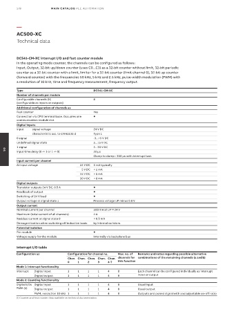
DC541-CM-XC interrupt I/O and fast counter module
In the operating mode counter, the channels can be configured as follows:
Input, Output, 32-bit up/down counter (uses C0...C3) as a 32-bit counter without limit, 32-bit periodic
counter as a 32-bit counter with a limit, limiter for a 32-bit counter (limit channel 0), 32-bit up counter
(forward counter) with the frequencies 50 kHz, 5 kHz and 2.5 kHz, pulse-width modulation (PWM) with
a resolution of 10 kHz, time and frequency measurement, frequency output.
Type DC541-CM-XC
Number of channels per module
Configurable channels DC 8
(configurable as inputs or outputs)
Additional configuration of channels as
Fast counter Yes
Connection via CPU terminal base. Occupies one
communication module slot
Digital inputs
Input signal voltage 24 V DC
characteristic acc. to EN 61132-2 Type 1
0 signal -3...+5 V DC
Undefined signal state 5...15 V DC
1 signal 5...30 V DC
Input time delay (0 -> 1 or 1 -> 0) 20 µs
05
Clamp to clamp - 300 µs with interrupt task
Input current per channel
At input voltage 24 V DC 5 mA typically
5 V DC > 1 mA
15 V DC > 5 mA
30 V DC < 8 mA
Digital outputs
Transistor outputs 24 V DC, 0.5 A
Readback of output
Switching of 24 V load
Output voltage at signal state 1 Process voltage UP minus 0.8 V
Output current
Nominal current per channel 500 mA at UP = 24 V
Maximum (total current of all channels) 4 A
Residual current at signal state 0 < 0.5 mA
Demagnetization when switching off inductive loads by internal varistors
Potential isolation
Per module
Voltage supply for the module Internally via backplane bus
Interrupt I/O table
Configuration as Configuration for channel no. Max. no. of Remarks and notes regarding possible alternative
Chan. Chan. Chan. Chan. Chan. channels for combinations of the remaining channels (a and b)
0 1 2 3 4-7 this function
Mode 1: Interrupt functionality
Interrupt Digital input 1 1 1 1 4 8 Each channel can be configured individually as interrupt
Digital output 1 1 1 1 4 8 input or output
Mode 2: Counting functionality
Digital I/Os Digital input 1 1 1 1 4 8 Usual input
PWM (1) Digital output 1 1 1 1 4 8 Usual output
PWM, resolution 10 kHz 1 1 1 1 4 8 Outputs and pulsed signal with and adjustable on-off ratio
(1) Counter and fast counter data available on technical documentation.