
Page 173 - PLC Automation
P. 173
AC500 -XC – PLC OPER ATING IN EXTREME CONDITIONS 171
—
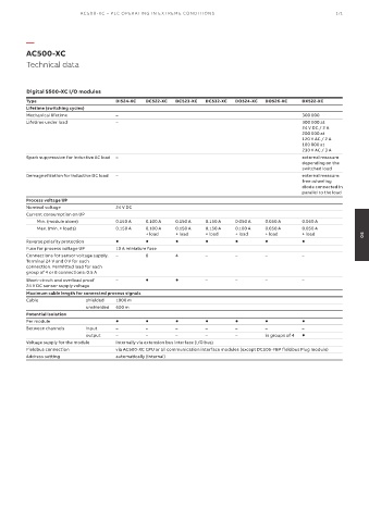
AC500-XC
Technical data
Digital S500-XC I/O modules
Type DI524-XC DC522-XC DC523-XC DC532-XC DO524-XC DO526-XC DX522-XC
Lifetime (switching cycles)
Mechanical lifetime – 300 000
Lifetime under load – 300 000 at
24 V DC / 2 A
200 000 at
120 V AC / 2 A
100 000 at
230 V AC / 3 A
Spark suppression for inductive AC load – external measure
depending on the
switched load
Demagnetization for inductive DC load – external measure:
free-wheeling
diode connected in
parallel to the load
Process voltage UP
Nominal voltage 24 V DC
Current consumption on UP
Min. (module alone) 0.150 A 0.100 A 0.150 A 0.150 A 0.050 A 0.050 A 0.050 A
Max. (min. + loads) 0.150 A 0.100 A 0.150 A 0.150 A 0.100 A 0.050 A 0.050 A
+ load + load + load + load + load + load 05
Reverse polarity protection
Fuse for process voltage UP 10 A miniature fuse
Connections for sensor voltage supply. – 8 4 – – – –
Terminal 24 V and 0 V for each
connection. Permitted load for each
group of 4 or 8 connections: 0.5 A
Short-circuit and overload proof – – – – –
24 V DC sensor supply voltage
Maximum cable length for connected process signals
Cable shielded 1000 m
unshielded 600 m
Potential isolation
Per module
Between channels input – – – – – – –
output – – – – – in groups of 4
Voltage supply for the module internally via extension bus interface (I/O bus)
Fieldbus connection via AC500-XC CPU or all communication interface modules (except DC505-FBP fieldbus Plug module)
Address setting automatically (internal)