
Page 96 - PLC Automation
P. 96
94 MAIN CATALOG PLC AUTOMATION
—
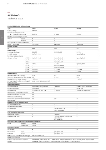
AC500-eCo
Technical data
Digital S500-eCo I/O modules
Type DX561 DX571 DC562
Supply voltage 24 V DC
Current consumption on UP
Max. (without load current) 0.005 A 0.050 A 0.010 A
Number of channels per module
Digital inputs 8 8 –
03
outputs 8 8 –
Configurable as Input or Output DC – – 16
Relays / Transistor Transistor Relay (n.o.) Transistor
Process voltage
DC 24 V 24 V 24 V
Digital inputs
Input signal voltage 24 V DC 24 V AC / DC 24 V DC
Input time delay typically 8 ms typically 8 ms
Input current per channel
At Input voltage 24 V DC typically 5 mA typically 5 mA typically 5 mA
24 V AC – typically 5 mA –
5 V AC – typically 1 mA –
5 V DC < 1 mA < 1 mA typically 1 mA
14 V AC – typically 2.7 mA –
27 V AC – typically 5.5 mA –
15 V DC > 2.5 mA > 2.5 mA > 2.5 mA
30 V DC < 6.5 mA < 6.5 mA < 8 mA
Output current
Nominal current per channel 0.5 A 2 A 0.5 A
Maximum (total current of all channels) 4 A 2 x 8 A 8 A
Residual current at signal state 0 < 0.5 mA – < 0.5 mA
Demagnetization when switching off must be performed externally
inductive loads
Switching frequency
For resistive load Limited by CPU cycle time 1Hz max. Limited by CPU cycle time
For inductive load 0.5 Hz max. – 0.5 Hz max.
For lamp load 11 Hz max. at max. 5 W 1 Hz max. 11 Hz max. at max. 5 W
Short circuit / overload proofness no
Overload indication (I > 0.7 A) no
Output current limiting no
Resistance against reverse feeding of no yes no
24 V signals
Output rating for different loads
For resistive load, max. – 2 A –
For inductive load, max. – – –
For lamp load – 200 W at 230 V AC –
30 W at 24 V DC
Lifetime (switching cycles)
Mechanical lifetime – 100 000 –
Lifetime under load – 100 000 at rated Load DC-13 –
according to
IEC 60947-5-1
Maximum cable length for connected process signals
Cable shielded 500 m
unshielded 150 m
Potential isolation
Per module –
Between the input – per group of 8 –
channels output – per group of 4 –
Voltage supply for the module's logic internal via I/O bus
Fieldbus connection
Suitable communication interface CI501-PNIO, CI502-PNIO, CI504-PNIO, CI506-PNIO, CI511-ETHCAT, CI512-ETHCAT, CI541-DP, CI542-DP,
module CI581-CN, CI582-CN, DC551-CS31, CI592-CS31, CI521-MODTCP, CI522-MODTCP