
Page 92 - PLC Automation
P. 92
90 MAIN CATALOG PLC AUTOMATION
—
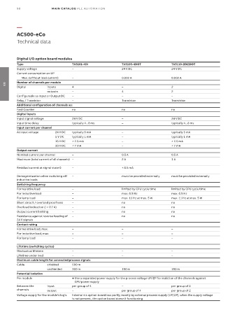
AC500-eCo
Technical data
Digital I/O option board modules
Type TA5101-4DI TA5105-4DOT TA5110-2DI2DOT
Supply voltage – 24 V DC 24 V DC
Current consumption on UP
Max. (without load current) – 0.002 A 0.002 A
Number of channels per module
Digital inputs 4 – 2
03
outputs – 4 2
Configurable as Input or Output DC – – –
Relay / Transistor – Transistor Transistor
Additional configuration of channels as:
Fast Counter no no no
Digital inputs
Input signal voltage 24 V DC – 24 V DC
Input time delay typically 4...8 ms – typically 4...8 ms
Input current per channel
At Input voltage 24 V DC typically 5 mA – typically 5 mA
5 V DC typically 1 mA – typically 1 mA
15 V DC > 2.5 mA – > 2.5 mA
30 V DC < 7 mA – < 7 mA
Output current
Nominal current per channel – 0.5 A 0.5 A
Maximum (total current of all channels) – 2 A 1 A
Residual current at signal state 0 – < 0.5 mA
Demagnetization when switching off – must be provided externally must be provided externally
inductive loads
Switching frequency
For resistive load – limited by CPU cycle time limited by CPU cycle time
For inductive load – max. 0.5 Hz max. 0.5 Hz
For lamp load – max. 11 Hz at max. 5 W max. 11 Hz at max. 5 W
Short circuit / overload proofness – no no
Overload indication (I > 0.7 A) – no no
Output current limiting – no no
Resistance against reverse feeding of – no no
24 V signals
Contact rating
For resistive load, max. – – –
For inductive load, max. – – –
For lamp load – – –
Lifetime (switching cycles)
Mechanical lifetime – – –
Lifetime under load – – –
Maximum cable length for connected process signals
Cable shielded 500 m
unshielded 300 m 150 m 150 m
Potential isolation
Per module Use a separated power supply for the process voltage UP/ZP for isolation of the channels against
CPU power supply
Between the input per group of 4 – per group of 2
channels output – per group of 4 per group of 2
Voltage supply for the module's logic internal via option board bus partly, mostly by external process supply (UP/ZP), when the supply voltage
is not present, the option board doesn't functioning