
Page 91 - PLC Automation
P. 91
AC500 -ECO – ENTRY LEVEL PLC SOLUTIONS 89
—
AC500-eCo
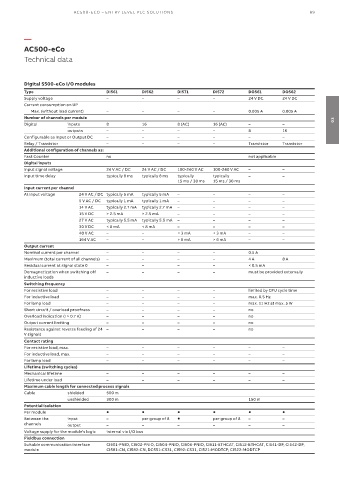
Technical data
Digital S500-eCo I/O modules
Type DI561 DI562 DI571 DI572 DO561 DO562
Supply voltage – – – – 24 V DC 24 V DC
Current consumption on UP
Max. (without load current) – – – – 0.005 A 0.005 A
Number of channels per module 03
Digital inputs 8 16 8 (AC) 16 (AC) – –
outputs – – – – 8 16
Configurable as Input or Output DC – – – – – –
Relay / Transistor – – – – Transistor Transistor
Additional configuration of channels as:
Fast Counter no not applicable
Digital inputs
Input signal voltage 24 V AC / DC 24 V AC / DC 100-240 V AC 100-240 V AC – –
Input time delay typically 8 ms typically 8 ms typically typically – –
15 ms / 30 ms 15 ms / 30 ms
Input current per channel
At Input voltage 24 V AC / DC typically 5 mA typically 5 mA – – – –
5 V AC / DC typically 1 mA typically 1 mA – – – –
14 V AC typically 2.7 mA typically 2.7 mA – – – –
15 V DC > 2.5 mA > 2.5 mA – – – –
27 V AC typically 5.5 mA typically 5.5 mA – – – –
30 V DC < 8 mA < 8 mA – – – –
40 V AC – – < 3 mA < 3 mA – –
164 V AC – – > 6 mA > 6 mA – –
Output current
Nominal current per channel – – – – 0.5 A
Maximum (total current of all channels) – – – – 4 A 8 A
Residual current at signal state 0 – – – – < 0.5 mA
Demagnetization when switching off – – – – must be provided externally
inductive loads
Switching frequency
For resistive load – – – – limited by CPU cycle time
For inductive load – – – – max. 0.5 Hz
For lamp load – – – – max. 11 Hz at max. 5 W
Short circuit / overload proofness – – – – no
Overload indication (I > 0.7 A) – – – – no
Output current limiting – – – – no
Resistance against reverse feeding of 24 – – – – no
V signals
Contact rating
For resistive load, max. – – – – – –
For inductive load, max. – – – – – –
For lamp load – – – – – –
Lifetime (switching cycles)
Mechanical lifetime – – – – – –
Lifetime under load – – – – – –
Maximum cable length for connected process signals
Cable shielded 500 m
unshielded 300 m 150 m
Potential isolation
Per module
Between the input – per group of 8 per group of 8 – –
channels output – – – – – –
Voltage supply for the module's logic internal via I/O bus
Fieldbus connection
Suitable communication interface CI501-PNIO, CI502-PNIO, CI504-PNIO, CI506-PNIO, CI511-ETHCAT, CI512-ETHCAT, CI541-DP, CI542-DP,
module CI581-CN, CI582-CN, DC551-CS31, CI592-CS31, CI521-MODTCP, CI522-MODTCP