
Page 93 - PLC Automation
P. 93
AC500 -ECO – ENTRY LEVEL PLC SOLUTIONS 91
—
AC500-eCo
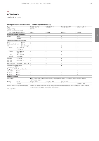
Technical data
Analog I/O option board modules – Preliminary information (1)
Type TA5120-2AI-UI TA5122-2AI-TC TA5123-2AI-RTD TA5126-2AO-UI
Supply voltage 24 V DC
Current consumption on UP
Max. (without load current) 0.050 A 0.050 A 0.050 A 0.070 A
Number of channels per module 03
Analog inputs 2 2 2 –
outputs – – – 2
Inputs, individually configurable
0…10 V 12 bits – – –
0…20 mA, 4…20 mA 12 bits – – –
RTD 15 bits + sign – – 2 –
Pt100 -50…+400 °C – – –
(2/3- wire)
Pt1000 -50…+400 °C – – –
(2/3-wire)
Ni100 / -50…+150 °C – – –
Ni1000 (2/3-wire)
Resistor 0…150 Ω – –
NTC 10K, -40...+110 °C – – –
NTC 20K
Thermocouple Types J, K, T, N, S, E, R – – –
Resolution of temperature – – –
measurement 0.1 °C
Outputs, individually configurable
-10...+10 V 16 bits – – –
0…20 mA 16 bits – – –
4…20 mA 16 bits – – –
Potential isolation
Per module Use a separated power supply for the process voltage UP/ZP for isolation of the channels against
CPU power supply
Analog inputs per group of 2 per group of 2 per group of 2 –
outputs – – – per group of 2
Voltage supply for the module's logic internal via option board bus partly, mostly by extrenal process supply (UP/ZP), when the supply voltage
is not present, the option board doesn't functionin
(1) In preparation