
Page 52 - Motor protection and control Manual motor starters, contactors and overload relays
P. 52
2/26 ABB MOTOR PROTECTION AND CONTROL
—
MS116, MS132, MS165, MO132, MO165
Technical data
02
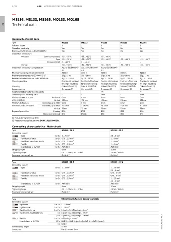
General technical data
Type MS116 MS132 MS165 MO132 MO165
Pollution degree 3 3 3 3 3
Phase loss sensitivity Yes Yes Yes No No
Disconnect function acc. to IEC/EN 60947-2 Yes Yes Yes Yes Yes
Ambient air temperature
Operation Open - compensated -25 ... +55 °C -25 ... +60 °C -25 ... +60 °C - -
Open -25 ... +70 °C -25 ... +70 °C -25 ... +60 °C -25 ... +60 °C -25 ... +60 °C
Enclosed (IB132) 0 ... +40 °C 0 ... +40 °C - - -
Storage -50 ... +80 °C -50 ... +80 °C -50 ... +80 °C -50 ... +80 °C -50 ... +80 °C
Ambient air temperature compensation Acc. to IEC/EN60947- Acc. to IEC/EN60947- Acc. to IEC/EN60947- - -
4-1 4-1 4-1
Maximum operating altitude permissible 2000 m 2000 m 2000 m 2000 m 2000 m
Resistance to shock acc. to IEC 60068-2-27 25g / 11 ms 25g / 11 ms 25g / 11 ms 25g / 11 ms 25g / 11 ms
Resistance to vibrations acc. to IEC 60068-2-6 5g / 3 ... 150 Hz 5g / 3 ... 150 Hz 5g / 3 ... 150 Hz 5g / 3 ... 150 Hz 5g / 3 ... 150 Hz
Mounting position Position 1-6 (optional Position 1-6 (optional Position 1-6 (optional Position 1-6 (optional Position 1-6 (optional
for single mounting) for single mounting) for single mounting) for single mounting) for single mounting)
Mounting DIN-rail (EN 60715) DIN-rail (EN 60715) DIN-rail (EN 60715) DIN-rail (EN 60715) DIN-rail (EN 60715)
Group mounting On request (2) On request (2) On request (2) On request (2) On request (2)
Recommended screw for mounting plate - - M4 - M4
Screw torque for mounting plate - - 2 Nm - 2 Nm
Minimum distance to other Horizontal 0 mm 0 mm 0 mm 0 mm 0 mm
units same type Vertical 150 mm 150 mm 150 mm 150 mm 150 mm
Minimum distance to Horizontal, up to 400 V 0 mm 0 mm 0 mm 0 mm 0 mm
electrical conductive board Horizontal, up to 690 V > 1.5 mm > 1.5 mm > 1.5 mm > 1.5 mm > 1.5 mm
Vertical 75 mm 75 mm 75 mm 75 mm 75 mm
Degree of protection Housing IP20 IP20 IP20 IP20 IP20
Main circuit terminals IP10 IP10 (1) IP10 IP10 IP10
(1) Push-in Spring terminals : IP20
(2) Please refer to application note: 2CDC131183M0201
Connecting characteristics - Main circuit
Type MS116 ≤ 16 A MS116 ≥ 20 A
Connecting capacity
Rigid 1 or 2 x 1 ... 4 mm² 2.5 ... 6 mm²
Flexible with ferrule 1 or 2 x 0.75 ... 2.5 mm² 1 ... 6 mm²
Flexible with insulated ferrule 1 or 2 x 0.75 ... 2.5 mm² 1 ... 6 mm²
Flexible 1 or 2 x 0.75 ... 2.5 mm² 1 ... 6 mm²
Stranded acc. to UL/CSA 1 or 2 x AWG 16-12 AWG 16-8
Stripping length 9 mm 10 mm
Tightening torque 0.8 ... 1.2 Nm / 10 … 12 Ib.in 2.0 Nm / 18 Ib.in
Recommended screwdriver Pozidriv 2 Pozidriv 2
Type MS132 ≤ 10 A MS132 ≥ 12 A
Connecting capacity
Rigid 1 or 2 x 1 ... 4 mm² 1 ... 2.5 mm²
2.5 ... 6 mm²
Flexible with ferrule 1 or 2 x 0.75 ... 2.5 mm² 0.75 ... 6 mm²
Flexible with insulated ferrule 1 or 2 x 0.75 ... 2.5 mm² 0.75 ... 6 mm²
Flexible 1 or 2 x 0.75 ... 2.5 mm² 1 ... 2.5 mm²
2.5 ... 6 mm²
Stranded acc. to UL/CSA 1 or 2 x AWG 16-12 AWG 16-8
Stripping length 9 mm 10 mm
Tightening torque 0.8 ... 1.2 Nm / 10 … 12 Ib.in 2.0 Nm / 18 Ib.in
Recommended screwdriver Pozidriv 2 Pozidriv 2
Type MS132-K with Push-in Spring terminals
Connecting capacity
Rigid solid 1 or 2 x 1 ... 2.5 mm²
Rigid stranded 1 or 2 x 1 ... 6 mm²
Flexible with ferrule 1 or 2 x 1 (push-in) / 0.5 (spring) ... 4 mm²
Flexible with insulated ferrule 1 x 1 (push-in) / 0.5 (spring) ... 4 mm²
1/2 x 1 (push-in) / 0.5 (spring) ... 2.5 mm²
Flexible 1 or 2 x 0.5 (spring) ... 4 mm²
Stranded acc. to UL/CSA 1/2 x AWG 18 ... AWG 10 (push-in) / AWG 18 ... AWG 8 (spring) 2CDC131062C0201 - Rev. B
1 x AWG 8
Wire stripping length 12 mm
Screwdriver Flat Ø 3 mm x 0.5 mm