Page 218 - EPR Catalog 2015
P. 218

CP-E range
   Benefits and advantages

   Characteristics                                                  Benefits

   – Output voltages 5 V, 12 V, 24 V, 48 V DC                       Signalling output/contact 1
   – Adjustable output voltages                                     The CP-E range 24 V devices > 18 W offer an output/contact
   – Output currents 0.625 A / 0.75 A / 1.25 A / 2.5 A / 3 A /      for monitoring of the output voltage and remote diagnosis.

      5 A / 10 A / 20 A

3  –  Power range 15 W, 18 W, 30 W, 60 W, 120 W, 240 W, 480 W       Wide range input 2
   –  High efficiency of up to 90 %                                 Optimised for world-wide applications: The CP-E power
   –  Low power dissipation and low heating                         supplies can be supplied within a wide range of AC or DC
   –  Free convection cooling (no forced cooling with ventilators)  voltage.
   –  Ambient temperature range during operation -40...+70 °C

   – Open-circuit, overload and short-circuit stable                Adjustable output voltage 3
   – Integrated input fuse                                          The CP-E range types feature a continuously adjustable
   – U/I characteristic curve on devices > 18 W                     output voltage. Thus, they can be optimally adapted to the
                                                                    application, e.g. compensating the voltage drop caused by a
      (fold-forward behaviour at overload – no switch-off)          long line length.
   – Redundancy units offering true redundancy
   – LED(s) for status indication

      – Signalling output/contact for output voltage OK             Redundancy units 4
                                                                    For decoupling of parallelized power supply units ͨ 40 V.
          Transistor on 24 V devices > 18 W and < 120 W             Thus, true redundancy can be achieved.
                                                                    Further information about redundancy unit on page 51.
      – Solid-state on 24 V devices ͧ 120 W
   – Approvals / Marks

      (depending on device, partly pending):

   – A, H, R, E / a, b

      12 3 4

                    2CDC 276 008 F0006
                                                                                                             2CDC 276 009 F0006
                                                                                                                                                                                                         2CDC 276 008 F0006
                                                                                                                                                                                                                                                                                                       2CDC 271 006 F0003

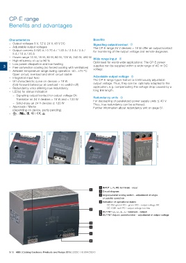
                                                                                                                        1 INPUT L, N, PE: terminals - input

                                                                                            1 2 Circuit diagram

                                                                                                                        3 single/parallel: sliding switch - adjustment of single
                                                                                                                                    or parallel operation

                                                                                                                        4 Indication of operational states
                                                                                                                                          DC ON: green LED - green LED - output voltage OK

                                                                                                           2 DC LOW: red LED - output voltage too low
                                                                                                                        5 OUTPUT L+, L+, L-, L-: terminals - output
                                                                                                                                    OUTPUT Adjust: potentiometer - adjustment of output voltage

                                                                                                           3
                                                                                                           4

                                                                                                                                      5

   3/19 ABB | Catalog Electronic Products and Relays 2015 | 2CDC 110 004 C0210
   213   214   215   216   217   218   219   220   221   222   223