
Page 222 - EPR Catalog 2015
P. 222
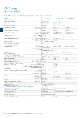
CP-E range
Technical data

Data at Ta = 25 °C, Uin = 230 V AC and rated values, unless otherwise indicated

Type                                                                  CP-E 24/0.75                             CP-E 24/1.25               CP-E 24/2.5
                                                                                                                      L, N
Input circuit                                                   100-240 V AC
Rated input voltage Uin                                         90-264 V AC /                            85-264 V AC /
Input voltage range                                             120-375 V DC                             90-375 V DC

        Frequency range AC                                      47-63 Hz
        Typical input current
                                                                at 115 V AC 335 mA                       560 mA                    1060 mA
3 Typical power consumption                                                                                                        590 mA
                                                 at 230 V AC 210 mA                                      330 mA                    69.2 W
        Inrush current limiting                                                                                                    20 A (max. 3 ms)
                                                                22.8 W                                   36.7 W                    40 A (max. 3 ms)
        Discharge current
                                                                at 115 V AC 10 A (max. 3 ms)             20 A (max. 3 ms)
        Power failure buffering time
                                                 at 230 V AC 18 A (max. 3 ms)                            40 A (max. 3 ms)
        Internal input fuse
        Power factor correction (PFC)            input / output 0.25 mA

                                                                input / PE 3.5 mA

                                                                at 115 V AC min. 20 ms                   min. 20 ms

                                                 at 230 V AC min. 75 ms                                  min. 30 ms

                                                                2 A slow-acting / 250 V AC

                                                                no

Indication of operational states                                green LED OK: V:                         OUTPUT OK: V: output voltage OK
Output voltage                                                                   output voltage OK       --

                                                                   red LED LOW: V:
                                                                                 output voltage too low

Output circuit                                                              L+,L-                                          L+, L+, L-, L-
Rated output voltage                                            24 V DC

Tolerance of the output voltage                                 0 ... +1 %

Adjustment range of the output voltage                          21.6-28.8 V DC                           24-28 V DC

Rated output power                                              18 W                                     30 W                      60 W

Rated output current Ir                                     Ta ͨ 60 °C 0.75 A                            1.25 A                    2.5 A
Derating of the output current                   60 °C < Ta ͨ 70 °C 2.5 %/°C                             transistor

Signalling output for output voltage OK                          DC OK -

Maximum deviation with                           load change statical ±2 %                               ±0.5 %

                                         change of output voltage within the ±1 %                        ±0.5 %
                                                               input voltage range
Control time
                                                                                             < 2 ms

Starting time after applying the supply voltage               at Ir max. 1 s
                                                 with 3500 μF -
                                                                                                         max. 2 s                  -

                                                 with 7000 μF max. 1.5 s                                 -                         max. 1.5 s

Rise time                                        at rated load max. 150 ms

                                                 with 3500 μF -                                          max. 500 ms               -

                                                 with 7000 μF max. 500 ms                                -                         max. 500 ms

Fall time                                                       max. 150 ms

Residual ripple and switching peaks              BW = 20 MHz 50 mV

Parallel connection                                             yes, to enable redundancy
Series connection                                               yes, to increase voltage
Resistance to reverse feed                                      1 s - max. 35 V DC

Output circuit - No-load, overload and short-circuit behaviour  Hiccup-mode                              U/I characteristic curve

Characteristic curve of output

Short-circuit protection                                        continuous short-circuit proof

Short-circuit behaviour                                         Hiccup-mode                              continuation with output power limiting

Overload protection                                             output power limiting

No-load protection                                              continuous no-load stability

Starting of capacitive loads                                    7000 μF                                  3500 μF                   7000 μF

3/23 ABB | Catalog Electronic Products and Relays 2015 | 2CDC 110 004 C0210