
Page 85 - PLC Automation
P. 85
AC500 -ECO – ENTRY LEVEL PLC SOLUTIONS 83
—
AC500-eCo
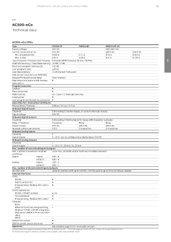
Technical data
AC500-eCo CPUs
Type PM564-TP PM564-RP PM564-RP-AC
Supply voltage 24 V DC 100-240 V AC
Current consumption on 24 V DC 100 V AC 240 V AC
Min. (module alone) 0.095 A 0.11 A 0.02 A 0.011 A
Max. (I/Os) 0.21 A 0.24 A 0.21 A 0.125 A
Type of processor / Processor clock frequency Freescale ARM Processor 32-bit / 50 MHz 03
Total RAM memory / Total Flash memory 16 MB / 4 MB
Total user program memory (3) 142 kB
User program code 128 kB
User data memory 14 kB thereof 2 kB saved
Web server's data for user RAM disk
Data buffering (of saved data) flash memory
Real-time clock (option with battery
back-up) (1)
Program execution
Cyclical
Time controlled
Multi tasking no, 1 task + 1 interrupt task max.
Interruption
User program protection by password
Cycle time for 1 instruction (minimum)
Binary/Word/ Floating 0.08 µs / 0.1 µs / 1.2 µs
Onboard digital inputs
Channels 6 (including 2 counter inputs, or up to 4 interrupt inputs)
Signal voltage 24 V DC
Onboard digital outputs
Channels 6 (including 2 PWM outputs for types with transistor outputs)
Relay / Transistor Transistor Relay Relay
Rated voltage 24 V DC 240 V AC 240 V AC
Nominal current per channel 0.5 A 2 A resistive 2 A resistive
Onboard analog inputs
Channels 2
signal ranges 0...10 V / can be configured as digital input 24 V DC
Onboard analog outputs
Channels 1
signal ranges 0...10 V / 0...20 mA / 4...20 mA
Max. number of centralized inputs/outputs
Max. number of extension modules up to max. 10 (S500 and/or S500-eCo modules allowed)
on I/O bus
Digital inputs 320 + 8
outputs 320 + 6
Analog inputs 160 + 2
outputs 160 + 1
Max. number of decentralized inputs/outputs
On CS31 bus up to 31 stations with up to 120 DI / 120 DO each or up to 32 AI/32 AO per station
Internal interfaces
COM1
RS485
Sub-D connection
Programming, Modbus-RTU, ASCII,
CS31
COM2 (option) (2)
RS485 / RS485 isolated /
Terminal block
Programming, Modbus-RTU, ASCII
Ethernet
RJ45 –
Ethernet functions: Programming, –
Modbus TCP/IP, UDP/IP, integrated
Web server, DHCP, FTP server, SNTP
client
SMTP –
RUN/STOP switch
LED for power, status and error
Approvals See detailed page 272 or www.abb.com/plc
(1) Real-time clock requires optional TA561-RTC or TA562-RS-RTC. (2) COM2 requires TA562-RS-RTC, TA562-RS or new TA569-RS-ISO.
(3) Total user program memory: contains user program code, data and web server