Page 431 - Entrelec Terminal Blocks Master Catalog
P. 431

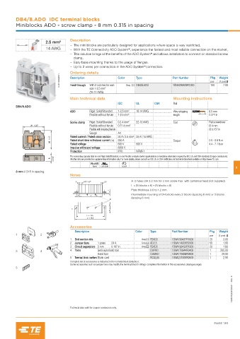
DB4/8.ADO  IDC terminal blocks
         Miniblocks ADO - screw clamp - 8 mm 0.315 in spacing


                                    Description
                        2.5 mm²
                                       – The mini blocks are particularly designed for applications where space is very restricted,
                        14 AWG         – With the TE Connectivity ADO System , experience the fastest and most reliable connection on the market,
                                                                 ®
                                                                            ®
                                       – This solution brings all the benefits of the ADO System  and allows installators to connect on standard screw
                                      clamp,
                                       – Easy base mounting thanks to the usage of flanges.
                                                                        ®
                                       – Up to 2 wires per connection in the ADO System connection.
                                    Ordering details
                              1SNC163059F0014  Description  Color    Type              Part Number       Pkg  Weight
                                                                                                              (1 pce) g
                                                                                                         pce
                                              With 2 notches for wire
                                    Feed-through
                                              size 1-2.5 mm   2  Grey  DB4/8.ADO       1SNA299509R1300   100    7.00
                                              (16-14 AWG)
                                    Main technical data                                Mounting instructions
                                                            IEC      UL       CSA      Rail
         DB4/8.ADO
                                    ADO       Rigid: Solid/Stranded  1-2.5 mm²  16-14 AWG  Wire stripping   9.5 mm
                                              Flexible without ferrule  1-2.5 mm²      length            0.374 in

                                    Screw clamp  Rigid: Solid/Stranded  0.2-4 mm²  22-10 AWG  Tool       Flat screwdriver
                31  1.22"                     Flexible without ferrule  0.22-4 mm²                       Ø 4 mm
                                              Flexible with insulated ferrule                            Ø 0.157 in
                                              Gauge         A4
                                                            24 A / 2.5 mm² 25 A / 14 AWG
                                    Rated current / Rated cross section
                             28  1.10"  Rated short-time withstand current (1s)  300 A  600 V  Torque    0.5 - 0.8 N.m
                                                            800 V
                                                                                                         4.4 - 7.1 lb.in
                                    Rated voltage
                                    Impulse withstand voltage  8000 V
                                    Protection              IP20     NEMA 1
                            0.315"  The connecting capacity data for one Rigid: Solid/Stranded, or one Flexible conductor (when applicable) is a mandatory information required by IEC, UL and CSA standards (Copper conductors).
                          8         All other data are provided as supplementary information only. For more details, please consult our CB, UL or CSA certificates and technical datasheet available on http://www.TE.com
                                               RoHS  USR CNR  Gost R                                                  6
         8 mm 0.315 in spacing
                                    Notes
                                                                  A: 2 holes DIA 3.2 mm for 3 mm screw max. with cylindrical head (not supplied).
                                            /
                                                                  L = (N blocks x 6) + (N blocks x 8)
                                                                  Plate thickness 0.6 to 1.2 mm
                                                                  Intermediate mounting of DH blocks every 2 blocks (spacing 8 mm) or 3 blocks
                                                                  (spacing 6 mm)
                                                       B

                                     A


                                    Accessories
                                      Description                   Color   Type      Part Number        Pkg  Weight
         1           2                                                                                   pce  (1 pce) g
                                    1  End section kits                Grey  FEAD3    1SNA199437R1600    20     3.00
                                    2  Jumper bars  1 poles  24 A      Grey  AD2.5    1SNA114205R2000    50     1.60
                                    3  Circuit separators 5 mm  0.197 in  Grey  FEAD5  1SNA199433R1200   20     1.80
         3           4              4  Tools     Semi automatic tool        OUPAD     1SNA178944R0400    1    205.00
                                                 Hand tool                  OUMAD     1SNA179466R0600    1     29.00
                                    5  Terminal block markers Blank card    RCAL85    1SNA237000R0500    1      2.90
                                    Complete list of accessories is indicated in the terminal block datasheet.
                                    Some accessories such as jumper bars may modify the terminal block’s ratings: complete information in the accessories catalogue pages.
         5

                                                                                                                    1SNC163037S0201 - Rev. A


                                    Technical data valid for copper conductors only.


                                                                                                           PAGE 139
   426   427   428   429   430   431   432   433   434   435   436