
Page 423 - Entrelec Terminal Blocks Master Catalog
P. 423
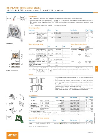
DS4/8.ADO  IDC terminal blocks
         Miniblocks ADO - screw clamp - 8 mm 0.315 in spacing


                                    Description
                        2.5 mm²
                                       – The mini blocks are particularly designed for applications where space is very restricted,
                        14 AWG         – With the TE Connectivity ADO System , experience the fastest and most reliable connection on the market,
                                                                 ®
                                       – This solution brings all the benefits of the ADO System  and allows installators to connect on standard screw
                                                                            ®
                                      clamp,
                                                                        ®
                                       – Up to 2 wires per connection in the ADO System connection.
                                    Ordering details        Color    Type              Part Number       Pkg  Weight
                                    Description
                               1SNC163080F0014  Feed-through  With rib and 2 notches for   Grey  DS4/8.ADO  1SNA299493R2300  pce  (1 pce) g
                                                                                                         100
                                                                                                                7.00
                                              wire size 1-2.5 mm²
                                              (16-14 AWG)
                                              Without rib for TB assembly   Grey  DSE4/8.ADO  1SNA299557R0200  20  7.00
                                              extremity and 2 notches for
                                              wire size 1-2.5 mm²
                                              (16-14 AWG)
         DS4/8.ADO
                                    Main technical data                                Mounting instructions
                                                            IEC      UL       CSA      Rail              TH 35-7.5,
                                                                                                         TH 35-15
                                    ADO       Rigid: Solid/Stranded  1-2.5 mm²  16-14 AWG  Wire stripping   9.5 mm
                 42.3  1.66"
                  31  1.22"                   Flexible without ferrule  1-2.5 mm²      length            0.37 in
                           43  1.69"     35.5  1.39"  Screw clamp  Rigid: Solid/Stranded  0.2-4 mm²  22-10 AWG  Tool  Flat screwdriver
                                              Flexible without ferrule
                                                            0.22-4 mm²
                                                                                                         Ø 4 mm
                                                                                                         Ø 0.157 in
                                              Flexible with insulated ferrule
                                              Gauge         A4
                                    Rated current / Rated cross section  24 A / 2.5 mm² 25 A / 14 AWG
                    20.6  0.81"     Rated short-time withstand current (1s)  300 A     Torque            0.5 - 0.8 N.m
                                    Rated voltage           1000 V   600 V                               4.4 - 7.1 lb.in
            DS             8  0.315"  Impulse withstand voltage
                                    Protection              IP20     NEMA 1
            DSE
                                    The connecting capacity data for one Rigid: Solid/Stranded, or one Flexible conductor (when applicable) is a mandatory information required by IEC, UL and CSA standards (Copper conductors).
                                    All other data are provided as supplementary information only. For more details, please consult our CB, UL or CSA certificates and technical datasheet available on http://www.TE.com  6
         8 mm 0.315 in spacing
                                               RoHS  USR CNR  Gost R
                                    Notes
                                                                     – End section FEAD1 to be mounted directly on the open part of the terminal
                                    DSE...  5 - 6 - 8  FEAD1
                                                                    block.
                                                                     – End terminal block DSE has to be mounted at the end of the terminal
                                                                    blocks assembly: it reduces its size, because it suppresses the insulation
                                                                    rib (- 4 mm).
                                               FEAD5
                                                                     – Nota: This terminal block cannot be accidently located anywhere else into
                                                                    the terminal block assembly (without locking holes)
                                                                     – Separator FEAD5  which snaps on the terminal blocks, separates and
                                                                    makes visible the different parts of the terminal blocks assembly.
                                     DS...  5 - 6 - 8
                                    Accessories
         1           2                Description                   Color   Type      Part Number        Pkg  Weight
                                                                                                         pce  (1 pce) g
                                    1  End stops  10 mm  0.394 in    Dark grey  BAM4  1SNK900001R0000    50    14.00
                                                 5.2 mm  0.205 in           BAZ1      1SNK900002R0000    50     5.30
         3           4              2  End sections  2.5 mm  0.098 in  Grey  FEAD1    1SNA199421R1600    20     1.30
                                    3  Jumper bars  1 poles  24 A      Grey  AD2.5    1SNA114205R2000    50     1.60
                                    4  Circuit separators 5 mm  0.197 in  Grey  FEAD5  1SNA199433R1200   20     1.80
                                    5  Tools     Semi automatic tool        OUPAD     1SNA178944R0400    1    205.00
                                                 Hand tool                  OUMAD     1SNA179466R0600    1     29.00
         5           6              6  Terminal block markers Blank card    RCAL85    1SNA237000R0500    1      2.90
                                    Complete list of accessories is indicated in the terminal block datasheet.
                                    Some accessories such as jumper bars may modify the terminal block’s ratings: complete information in the accessories catalogue pages.

                                    Ground IDC terminal blocks                                                      1SNC163029S0201 - Rev. A
                                    Description                   Color     Type      Part Number        Pkg  Weight
                                                                                                         pce  (1 pce) g
                                    Ground    Profile aligned with DS4/8.ADO  Green-yellow  DS4/8.P.ADO  1SNA199527R1000  100  8.00
                                    Technical data valid for copper conductors only.


                                                                                                            PAGE 131